A huge element of software and hardware design is figuring out how various components are going to fit together and talk to each other. This could be interfaces within a codebase like function names and signatures, networked components communicating via REST or gRPC, or the PCI-Express lanes between your processor and GPU. In today's episode, I'll be experimenting with designing a SystemVerilog module that can work with the classic TTL serial protocol.
Talking to my FPGA
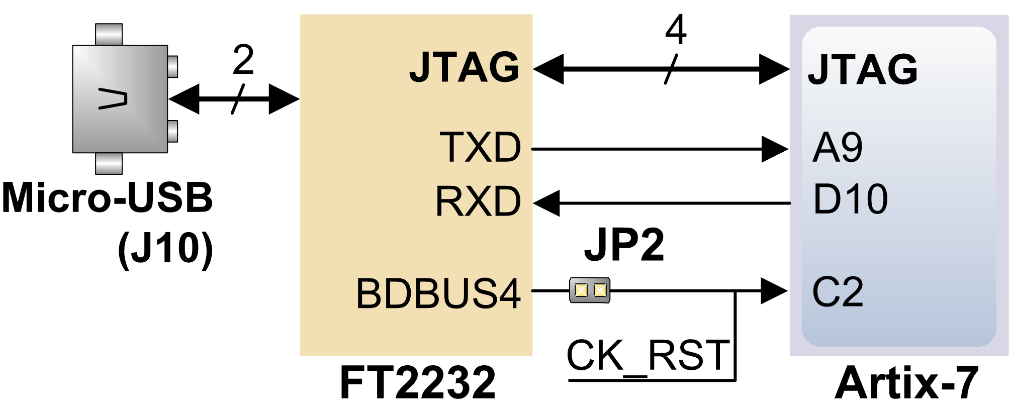
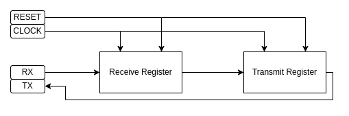
In some of my planned projects, I'm going to want a way to communicate between a digital design I've loaded onto my FPGA and my laptop. Here's the design that I'm working towards here:
For my target board, the Arty A-7, the easiest available option for me is serial since this board has a USB controller with rx/tx pins routed to the FPGA.
To kick things off, I'm going to start a Wiz project and map some IO pins. For this design I'll have the pins: rx and tx for serial, clk as my input clock using the 100mhz clock from the Arty board and reset to help make sure things initialize into a good state.
package_name = 'uart'
builder = 'vivado'
programmer = 'vivado'
target_part = 'xc7a35ticsg324-1L'
target_device = 'xc7a35t_0'
source_files = [
    'top.sv',
]
bitstream_path = 'uart.bit'

[pins]
tx = 'D10'
rx = 'A9'
clk = 'E3'
reset = 'C2'
I find it really easy to swap rx and tx by accident, especially in cases like this where the diagram above says TXD goes to A9. From the perspective of my module that is actually the rx line since that is the line I'll be receiving from, so I'll map those as such to help me keep their usage straight in my design.
I want to verify that my pins are working as expected, so before I start trying to build some kind of UART I'm going to just wire rx to tx to create a stupid-simple echo implementation for the serial communication.
module top (
  input wire clk,
  input wire reset,
  input wire rx,
  output wire tx
);

  assign tx = rx;

endmodule
I'll give this a wiz build to build it and a wiz program to slap it on my Arty-A7. I'll write a short Python script to use the serial port.
import serial

ttl = serial.Serial('/dev/ttyUSB1', 115200)
ttl.write(b"test!")
print(ttl.read(5).decode('utf-8'))
Lastly, I'll run that to make sure it works.
$ python test.py
test!
Perfect! I now have a working "echo" serial device, though so far I'd probably just call it a complicated way of jumping two pins together.
Building a UART
I'm not familiar with UART design techniques, but through trying to get this project to work I settled on a simple design that's based on some stateful shift registers. I'll have one register working on the RX side receiving data and one on the TX side sending data.
One of the big considerations for how I want this UART to work is going to be its baud rate. On this board I have a 100mhz input clock to work with, so I can very reliably time a 115200 baud communication. The approach is going to be very similar to a software bitbanging approach, but kind of simpler and very accurate by comparison.
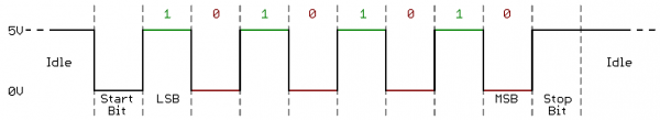
For this post I won't detail the TTL Serial protocol in full, as I think this Sparkfun tutorial covers that very nicely and it continues to be my go-to resource for UART protocol details. The most important part is the general transmission format, which in my case here will be with 3.3V TTL serial.
I'll build my design as a state machine. It will start at an initial state where we're waiting for the RX line to drop low to indicate the IDLE bit. At that detection, I'll reset and start a counter of clk transitions and at the right number of clock cycles I'll sample the RX line for data, easy enough!
I'll start this part of the design by build the core guts of my RX register:
module UartRxRegister (
    input clk,
    input reset,
    input rx,
    output logic available,
    output logic [7:0] data
);

  typedef enum {
    IDLE,
    BIT[8],
    STOP
  } RxState;

  RxState state;
  logic [13:0] counter;

  always @ (posedge clk or negedge reset) begin
    if (!reset) begin
      state <= IDLE;
      available <= 0;
    end
  end

endmodule
So far this module has it's inputs and outputs, an enum defining the RxState type along with the 10 states for this system (IDLE, BIT0 through BIT7 and STOP). I've also started added the reset logic to default state to IDLE and to set the available output flag low.
Next I'll start to shape out the state machine itself.
case (state)
  IDLE: begin
    if (!rx) begin
      state <= BIT0;
      available <= 0;
      counter <= 0;
    end
  end
  BIT0: begin
    state <= BIT1;
  end
  BIT1: begin
    state <= BIT2;
  end
  BIT2: begin
    state <= BIT3;
  end
  BIT3: begin
    state <= BIT4;
  end
  BIT4: begin
    state <= BIT5;
  end
  BIT5: begin
    state <= BIT6;
  end
  BIT6: begin
    state <= BIT7;
  end
  BIT7: begin
    state <= STOP;
  end
  STOP: begin
    state <= IDLE;
    available <= 1;
  end
endcase
With this state machine, the system should wait in IDLE until the rx serial line is brought low for the starting bit. Once the starting bit arrives, the system should begin transitioning through the other states in order until the STOP bit prepares the system to begin again.
Testing it Live
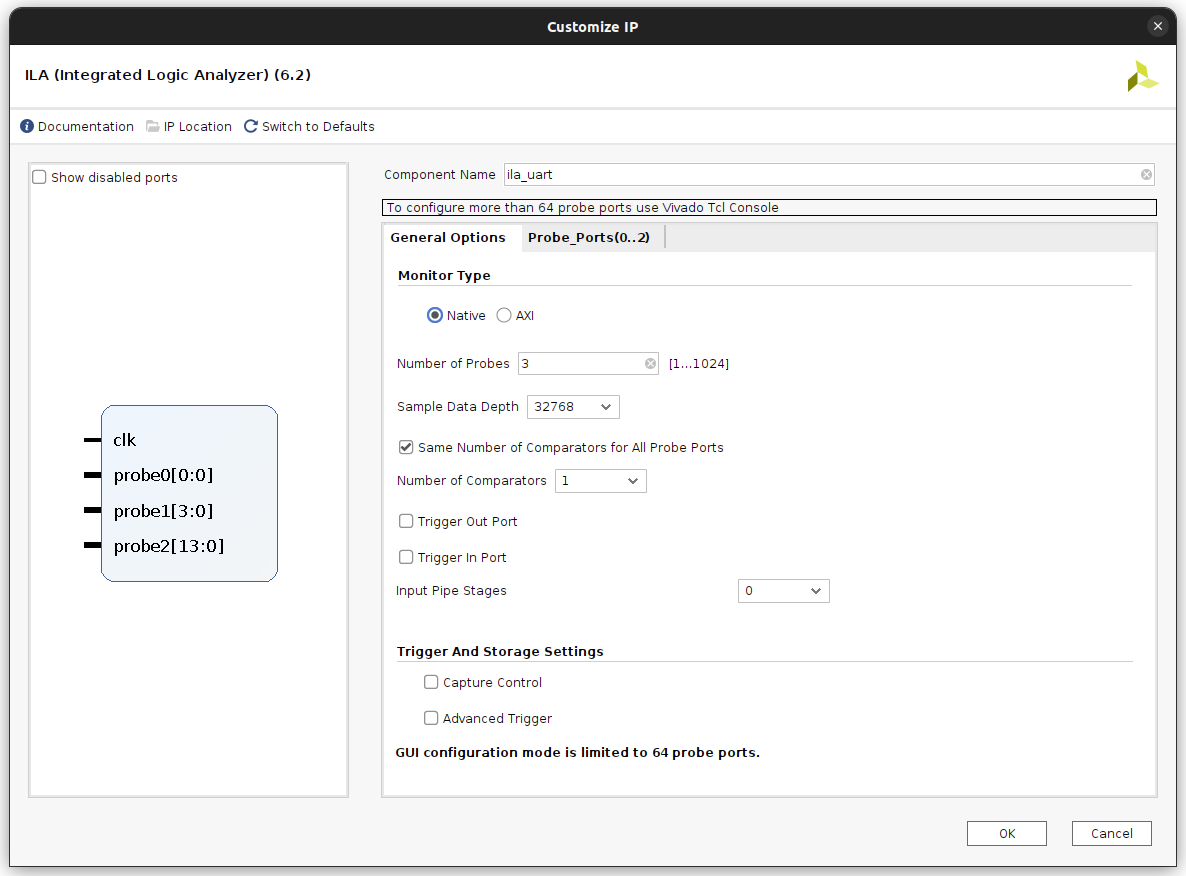
At this point I want to see how my state machine behaves when presented with some serial traffic, so I'm going to generate an ILA (integrated logic analyzer) core to debug my design with.
After giving my project a fresh wiz build, I'll open up the generated Vivado project and instantiate a new ILA core with 2 inputs: a 1-bit input I'll use for rx and a 4-bit value to monitor how the STATE register reacts to it and a 14-bit register for the counter.
I'll have vivado kick off the generator it uses to build the ILA, and add an instantiation of this new module in my rx module:
ila_uart debugger (
  .clk(clk),
  .probe0(rx),
  .probe1(state),
  .probe2(counter)
);
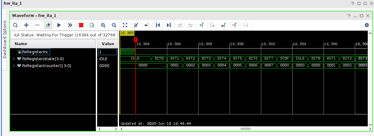
Then I'll build the bitstream in Vivado and run it along with the debugging stuff it generated. When I deploy the design via the Hardware Manager in Vivado it'll bring up the ILA's waveform viewer, where I'll see the design is stably in the IDLE state until rx goes low to indicate the start of a transmission.
Reading Time
With the state transitions working, I'll now work on triggering those transitions as close to the middle point of each bit as I can with my given input clock of 100Mhz. I'll refer again to the diagram from SparkFun.
If I want to read the value of the least significant bit, the ideal time to poll at "1.5 baud". Each next bit is 1 baud away until the stop bit, which we're not going to be using so the final transition from STOP to IDLE should happen at 0.5 baud after we read the most significant bit.
To determine how many of the 100Mhz clock cycles we should be waiting for at each transition, I whipped up a python script that spits out the numbers I'm looking for.
#!/usr/bin/env python3
input_clock = 100000000.0
baud = 115200.0

bauds_per_clock = input_clock / baud

for i in range(0, 8):
    next_step = int((1.5 + i) * bauds_per_clock)
    print(f"BIT{i}: {next_step}")

last_step = int(9 * bauds_per_clock)
print(f"STOP: {last_step}")
When ran this gives me:
BIT0: 1302
BIT1: 2170
BIT2: 3038
BIT3: 3906
BIT4: 4774
BIT5: 5642
BIT6: 6510
BIT7: 7378
STOP: 7812
I'll now add checks to each state so that when the counter hits that number it transitions to the next state, I'll also go ahead and read rx to set the appropriate bit in my output data register.
case (state)
  BIT0: begin
    if (counter == 1302) begin
      data[0] <= rx;
      available <= 0;
      state <= BIT1;
    end
  end
  BIT1: begin
    if (counter == 2170) begin
      data[1] <= rx;
      state <= BIT2;
    end
  end
  BIT2: begin
    if (counter == 3038) begin
      data[2] <= rx;
      state <= BIT3;
    end
  end
  BIT3: begin
    if (counter == 3906) begin
      data[3] <= rx;
      state <= BIT4;
    end
  end
  BIT4: begin
    if (counter == 4774) begin
      data[4] <= rx;
      state <= BIT5;
    end
  end
  BIT5: begin
    if (counter == 5642) begin
      data[5] <= rx;
      state <= BIT6;
    end
  end
  BIT6: begin
    if (counter == 6510) begin
      data[6] <= rx;
      state <= BIT7;
    end
  end
  BIT7: begin
    if (counter == 7378) begin
      data[7] <= rx;
      state <= STOP;
      available <= 1;
    end
  end
  STOP: begin
    if (counter == 7812) begin
      state <= IDLE;
    end
  end
endcase
BIT7 gets a little special treatment, as that's our last bit so at this point our transferred byte is available and I'll indicate that with the available output.
The reading side should be good to go now I think... I'll recustomize the ILA core to add probes for data and available so that I can see how they are changing as well.
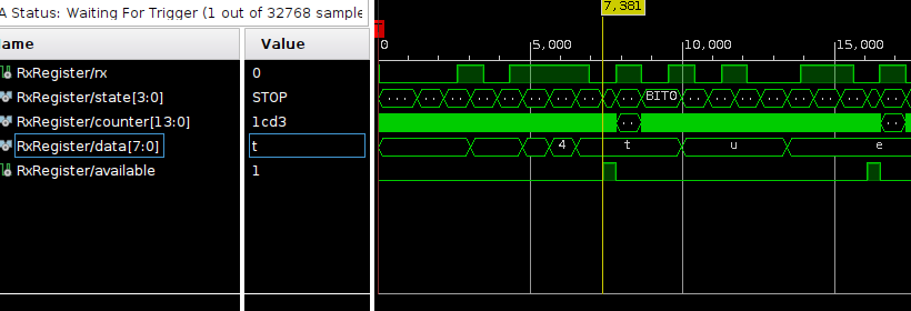
Perfect, the transitions are happening at the right times, and data holds the appropriate values when available is raised!
Writing Back
To wrap up this echoing UART design I'll implement the TX register in roughly the same way as the RX register, but basically in reverse. It'll take in clk and reset just like RX register, but the TX register will also have the inputs send and data for writing a byte out to its one output: tx.
module UartTxRegister (
    input clk,
    input reset,
    input send,
    input [7:0] data,
    output logic tx
);
The state enum is a little different as well. We'll still start in IDLE, but we'll need to bring tx low for 1 baud as the START bit. After that, we'll send out the data bits.
typedef enum {
  IDLE,
  START,
  BIT[8]
} TxState;
Within the module I have a state and counter just like before, but this time I'll also add a send_data register that will store the input data when send goes high.
TxState state;
logic [13:0] counter;
logic [7:0] send_data;
Now to implement the logic for sending. I'll add some additional outputs to my Python script to give me the clock times I'll need.
print("Writing times:")
first_step = int(bauds_per_clock)
print(f"START: {first_step}")

for i in range(0, 8):
    next_step = int((2 + i) * bauds_per_clock)
    print(f"BIT{i}: {next_step}")
Similar to before, this prints out my timing for when each state should transition to the next.
START: 868
BIT0: 1736
BIT1: 2604
BIT2: 3472
BIT3: 4340
BIT4: 5208
BIT5: 6076
BIT6: 6944
BIT7: 7812
Now to implement the always block. It'll start off with the reset logic followed by the state machine. It'll hold the counter to 0 and tx to 1 while reset or idle. When send is raised the value will be stored in send_data, the state transitions to START and the counter starts counting.
always @ (posedge clk) begin
  if (!reset) begin
    state <= IDLE;
    tx <= 1;
    counter <= 0;
  end else begin
    if (state == IDLE) begin
      counter <= 0;
      tx <= 1;
      if (send) begin
        state <= START;
        send_data <= data;
      end
    end else begin
      counter <= counter + 1;
      case (state)
        START: begin
          tx <= 0;
          if (counter == 868) begin
            state <= BIT0;
          end
        end
        BIT0: begin
          tx <= send_data[0];
          if (counter == 1736) begin
            state <= BIT1;
          end
        end
        BIT1: begin
          tx <= send_data[1];
          if (counter == 2604) begin
            state <= BIT2;
          end
        end
        BIT2: begin
          tx <= send_data[2];
          if (counter == 3472) begin
            state <= BIT3;
          end
        end
        BIT3: begin
          tx <= send_data[3];
          if (counter == 4340) begin
            state <= BIT4;
          end
        end
        BIT4: begin
          tx <= send_data[4];
          if (counter == 5208) begin
            state <= BIT5;
          end
        end
        BIT5: begin
          tx <= send_data[5];
          if (counter == 6076) begin
            state <= BIT6;
          end
        end
        BIT6: begin
          tx <= send_data[6];
          if (counter == 6944) begin
            state <= BIT7;
          end
        end
        BIT7: begin
          tx <= send_data[7];
          if (counter == 7812) begin
            state <= IDLE;
          end
        end
      endcase
    end
  end
end
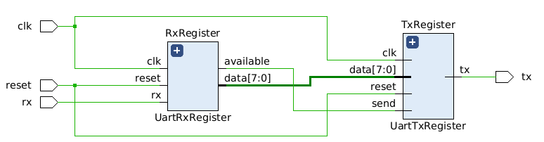
That should take care of the TX register. The last bit left to do is to wire it up on the top module.
module top (
  input wire clk,
  input wire reset,
  input wire rx,
  output wire tx
);

  logic available;
  logic [7:0] data;

  UartRxRegister RxRegister(clk, reset, rx, available, data);
  UartTxRegister TxRegister(clk, reset, available, data, tx);

endmodule
Now to hope it all works! I'll instantiate another ILA instance and watch all the good stuff in the top module.
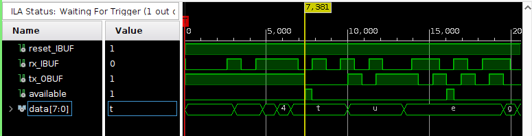
There it is, the UART successfully reads and echos back! This was a pretty large post, but if you made it to the end here I appreciate it and hope you enjoyed the post.