In the previous post, I implemented a single decimal digit display that used "hardware" pretty minimally. The digital logic side of the design simply split each bit of a byte to allow a software controlled means of controlling each segment of the display.
In this post I'll expand on this design and explore a few more core concepts in hardware tinkery.
The primary goal for this post is to use the 7-segment displays to view the hexademical values for the binary data we're delivering through the Telnet block. When I send an ASCII K to the design, I want to see the 4B displayed in the simulated displays.
What the Hex
In the last post I had a table for which segments should be lit for 0-9. I'll need A-F as well, so I'll add them to that table.
| Value | Segments | Hexadecimal |
|---|---|---|
0 | --543210 | 3F |
1 | -----21- | 06 |
2 | -6-432-0 | 5D |
3 | -6--3210 | 4F |
4 | -65--21- | 66 |
5 | -65-3-10 | 6B |
6 | -6543-10 | 7B |
7 | ----321- | 0E |
8 | -6543210 | 7F |
9 | -65-3210 | 6F |
A | -654321- | 7E |
B | -654--10 | 73 |
C | --543--0 | 39 |
D | -6-4-210 | 57 |
E | -6543--0 | 79 |
F | -6543--- | 78 |
My plan is to make a couple small components to organize my implementation for this. I'll start with a single 7-segment driver that takes a 4-bit (nibble) input and drives 1 segment. Once I have that, I'll combine two of them into 1 block that can drive 2 segments.
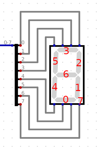
I'll start by planning out my driver design, first dropping a display in the schematic and making an input bus.
So now I need to light up the right segments based on the values of 4 inputs. I thought of a few different ways for how this could be done.
Logic Gates, Logically
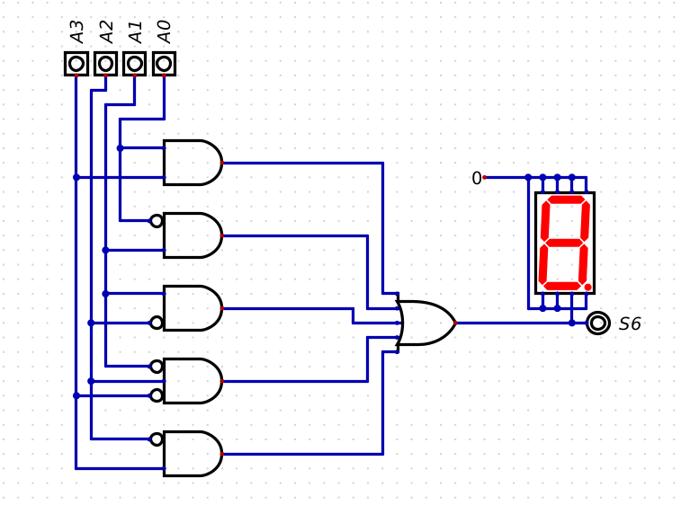
I decided to see what it'd take to light up segment 6 for the right inputs. I started by looking at which numbers should and should not be lit for this segment.
Should be lit:
| Hexadecimal | Binary |
|---|---|
2 | 0010 |
3 | 0011 |
4 | 0100 |
5 | 0101 |
6 | 0110 |
8 | 1000 |
9 | 1001 |
A | 1010 |
B | 1011 |
D | 1101 |
E | 1110 |
F | 1111 |
Should not be lit
| Hexadecimal | Binary |
|---|---|
0 | 0000 |
1 | 0001 |
7 | 0111 |
C | 1100 |
I don't see any obvious simple pattern for implementing this with logic gates. Since the display is lit 3/4 of the time, my quick implemention idea is to use 4-input AND gates with some inverted inputs to match each pattern that should not be lit, and input all of those into a 4-input NOR gate.
I'll roughly layout the logic gates and route 0 to the remaining segments for now.
Each gate will match a condition where the segment shouldn't be lit. For when a bit value I'm looking for is 0, I'll flip that invert on its way into the gate. I'll struggle a little bit to wire things up properly then give it a little bit of manual testing.
"Proper" engineering
While this solution only has 5 gates in my schematic, 4-input gates are basically each made of 3 gates. So this design would take at least 15 gates, before including the inverted bits... which is pretty inefficient. There are better, boolean-mathical ways of addressing this, and the simulator has a bit of tooling to assist in avoiding the maths.
If I add and name an output, and name the inputs, I can ask the analysis tool to do it's thing. It'll generate a truth table for me. At the bottom of that table I can find a simplified function that'll generate the same output. I can also bring up the Karnaugh map, though I don't find it particularly helpful here.
That's still... not exactly small is it?
I'm not particularly interesting in doing that 6 more times, so I'm going to change my approach.
Cheat Codes
Instead of going through all that, I'm going to use a LUT (Look-Up Table) to design this a bit more like the original software-oriented route. I'll toss all of this implementation out the door and wire a new LUT block into the design.
Next, I'll load up a file that contains the hex values of the digits.
v2.0 raw
3f
06
5d
4f
66
6b
7b
0e
7f
6f
7e
73
39
57
79
78
Well! That was a heck of a lot quicker and easier. I'll just tweak the inputs and outputs so that I can save this design and use it elsewhere.
Then I'll quickly make a dual-display variant, that simply takes in an 8-bit bus and outputs two segment busses. If I open straight to a new file, the simulator doesn't pick up my other files in the Components menu. If I choose a New embedded Circuit, it will find those files.
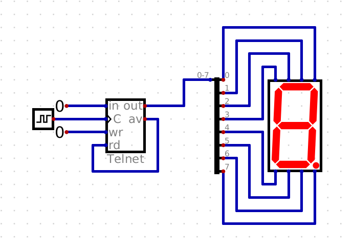
Finally, I'll go back into my Telnet schematic and wire up everything to use my new block. To keep things looking relatively tidy, I'll pre-wire the segments to space things out then collapse those individual signals into 4-bit busses. I'll then split the 8-bit segments out into top and bottom busses. I used the horizontal offset of the 8:4*2 splitters to help me visually remember that S1 is on the left and S0 on the right.
That Darn Impedence
With everything wired up, things do work, but there's a little bit of undesired behavior.
Before and after I send my sequence through the Telnet block, the displays will show a random value due to the inputs that aren't being driven to a valid state for reading.
I need somewhere to latch onto just the valid inputs at just the right times, which is exactly what flip-flops are here for!
Latches and flip-flops are circuits for storing bits of information. This playlist on YouTube covers the standard variants
I generally prefer the D-type flip-flops, as they are simple and good for registers. I just feed my data into D, and when C transitions from 0 to 1 the value will be stored and output on Q until the next rising clock (the opposite values will be output on the inverted Q, unused here)
I also added the AND gate here so that the flip-flop will only latch to the value when the av and clock signals are high. This still leaves me an unexpected result at the end of my sequence.
The problem here is that both the Telnet block and the flip-flop latch when the clock transitions to 1. Does the Telnet block update fast enough to allow this? Probably not.
Though, if I invert the clock the latching will happen one half-cycle after the Telnet block has updated its value. Giving the Telnet block a little time to change its output before storing it.
There we have it, a decently working hexadecimal display! With the goal complete I'll call it a wrap for this post.
I hope you enjoyed this post, stay tuned for the next one!
Bonus material
While you wait for the next post, here are a couple good videos to check out: