Programmable logic is my favorite concept in computing, integrated circuits that let you define hardware behavior. This is an excessively powerful concept that is just waiting for the open source community to do amazing things with.
For many hobby electronics projects, you can use a software-focused approach and use an Arduino or Raspberry Pi to accomplish a wide variety of tasks. I've enjoyed that approach but, I want to go a bit more off road than mere software allows. Programmable logic lets me, someone who should not [yet] be paid to design custom hardware, do it anyway!

I'd like to share a path that I think makes it a lot easier and more fun to get into. It'll start with tinkering in a virtualized hardware environment that lets you explore a bit more in the comfort of your own programming language.
Virtual Tinkering
I want to bring more software programmers into the world of tinkering with programmable logic, but jumping head first into HDL is kinda hard and it helps to have a lot more context. I found it was really helpful to play with some of schematic based logic design tools first, but what I could accomplish with them felt pretty quickly constrained.
I recently came across a digital logic designer and simulator tool called Digital, and it is pretty awesome. It's an open source, Java-based program that runs pretty simply on Linux, MacOS and Windows.
This tool has all the features I want in a simulator, plus a few extras that surprised and excited me. It has the core stuff like logic gates, buttons and LEDs, and a few nice higher level components like flip-flops, multiplexers and 7-segment displays and even an LED matrix! A few components I'd never seen in a free simulator before, like blocks for keyboard input, VGA, MIDI and blocks for VHDL and Verilog.
A couple blocks feel particularly ready for some mad computer science...
Setting the Stage
Digital is super easy to obtain and run, you can check here to see just how easy. When you first launch the program it'll offer a short tutorial that helps quickly acclimate to placing components in the schematic, wiring them together and simulating the design.
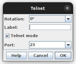
Start your new schematic and go to Components -> IO -> Peripherals and add a Telnet component.
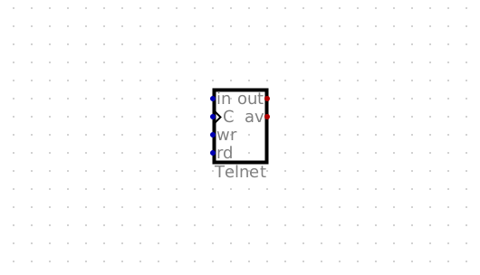
I chuckled when I saw the name Telnet, but I am definitely going to use this component because it sounds awesome. How does it work? I'll just hit play
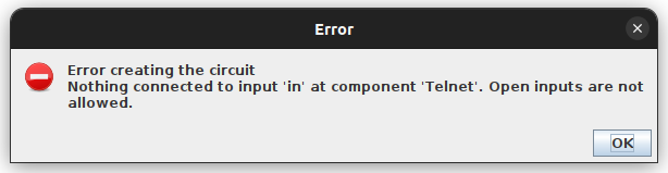
Alright, it's mad at me for not feeding it. It needs some inputs so I'll wire a button into all the inputs.
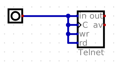
This will definitely work
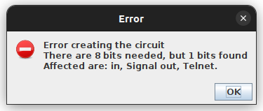
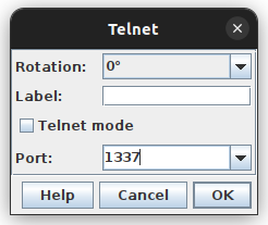
Okay fine, maybe some docs would be useful. If I right click on this component I get the following prompt.
I'm going to change a few settings while I'm here, like turning Telnet Mode off so that it's a simple TCP server and I'll pick 1337 since that's a not a privileged port.
And look a handy help button!
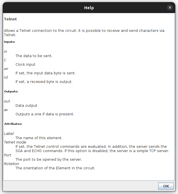
So based on what I'm seeing here, I'll wire up my inputs a bit more sanely. I don't plan on writing data out yet, so I'll set in and wr to 0, feed the output of a clock to C, and a basic input for rd
Next, I'll wire up a Terminal block as the output. I'll add a new button to enable the terminal, route the out from the Telnet block to the Data input, and plumb the same clock signal into C
I think we're looking about ready to go!
Hello Digital World
Now for the fun part, when I simulate this design I'll be able to connect to the Telnet block on 127.0.0.1:1337 and data I pass into that socket connection should emit from the block. I like that this lets me hook into my design, relatively simply, with any language of my choice.
My go-to language for quick hackyness is Python, so I'll write a little script to send some data:
#!/usr/bin/env python
from socket import create_connection

ADDRESS = ('127.0.0.1', 1337)

socket = create_connection(ADDRESS)
socket.sendall(b"Hello, Digital World!\n")
There's a slight problem before running this though. Before I even send input, activating the terminal will spit out some junk data. I'll enable my clock and show you want I mean:
If you notice, before I let the terminal body-block the schematic, the data in the line is Z. This state is called "high impedance", which basically means nothing is driving this signal and is also referred to as "floating". Effectively this means we're going to be getting some undefined behavior!
To address this, and make things a little bit more automatic, I'm going to route the available signal to both the enable input for the Terminal block and the rd (read) input of the Telnet block.
This should work a bit nicer. I'll now run my python script while the simulation is also going. The 1hz clock signal I sent before was painfully slow, so I'm going to crank that up to a whopping 10hz!
It works! I know it's a bit silly, but now I have this interface that I can use to interact with little simulated hardware designs. I think that's actually pretty nifty.
More Softwarification
Before wrapping this post, I want to use this pattern to do something a bit more hardware oriented. Certainly cat or nc can offer pretty similar functionality to this without all the fuss!
Considering the output is 8-bit, the first thing that comes to mind for me is the 7-segment display, which is more of an 8-segment display really! I can use each bit of a byte sent to the Telnet block to map directly to a display segment.
In the video below, I remove the Terminal bits and replace it with the 7-segment display. To open up the 8-bit out bus I'll use the Splitter/Merger component and take the 8-bit input and split it into 8 1-bit outputs, the 1*8 expression helps me specify this. Then I route the wires to the display
I definitely didn't practice this like a half dozen times to create the facade that I know what I'm doing...
I'll modify the output of my python script to light up 1 bit at a time. I've played enough with binary numbers to have picked up a few tricks so I'll just use some hexadecimal encoded characters for this.
#!/usr/bin/env python
from socket import create_connection

ADDRESS = ('127.0.0.1', 1337)

socket = create_connection(ADDRESS)
socket.sendall(b"\x00\x01\x02\x04\x08\x10\x20\x40\x80")
Running this while simulating, I can visually identify which bits goes to which segment.
It was a little handy to have a little video clip of this running too, so I could take a screenshot and label my semi-arbitrary segment numbering!
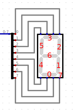
With this, I'll make one more reference for what segments I want lit for each number.
| Number | Segments | Hexadecimal |
|---|---|---|
0 | --543210 | 3F |
1 | -----21- | 06 |
2 | -6-432-0 | 5D |
3 | -6--3210 | 4F |
4 | -65--21- | 66 |
5 | -65-3-10 | 6B |
6 | -6543-10 | 7B |
7 | ----321- | 0E |
8 | -6543210 | 7F |
9 | -65-3210 | 6F |
For my final trick, I'll make a countdown. I'll tick down from 9 to 0, then flash the whole display a couple times with 0x00 and 0xFF.
#!/usr/bin/env python
from socket import create_connection

ADDRESS = ('127.0.0.1', 1337)

socket = create_connection(ADDRESS)
socket.sendall(b"\x00\x6f\x7f\x0e\x7b\x6b\x66\x4f\x5d\x06\x3f")
socket.sendall(b"\x00\xff\x00\xff\x00\xff")
I'm hoping that'll work!
It does!
With that, we have our little software foot in the door for some hardware tinkering. The Telnet block certainly won't easily translate to a real world design, but this pattern will be very useful for the tinkering to come. If nothing else, it allows for some experimentation through a mix of software and hardware!
I hope you enjoyed this post, stay tuned for the next one!
Bonus material
While you wait for the next post, here are a couple good videos to check out: